Copyright © 2007 - 2026, Richard Troy, For contact data Click Here.

Copyright © 2007 - 2026
Copyright © 2007
- 2026, Richard Troy, For contact data Click Here. 
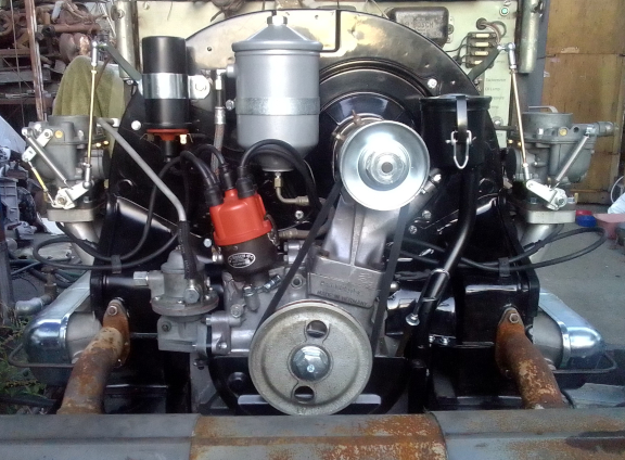 Case Number 60884x*
 This early T-6 B era 356 engine has been rebuilt as if it
was a B era 1600S using two of the last genuine 356 Carburetor
Rescue rebuilt Super Zeniths. It's got the fairly ubiquitous "big
bore kit" and the late C/SC/912 rods. It has has been fully
balanced for smooth running, long life, and a few more HP.
Then, it was run-in and tuned on my
Stuska water-brake engine dynamometer as per Porsche
factory specifications as outlined in the Workshop Manual,
operations 52 EN, 53 EN, and 54 EN, pages E83 and E84.
ABOVE: Here it is right before startup as a turn-key engine. It still had a few details to be addressed when this image was snapped.
Either the earlier Wire Mesh or later Canister Style
air cleaners and all the surrounding tinware are on hand if you
need some of these bits for this engine; these were not provided
for two reasons. First, over decades I've realized most of us
looking for an engine, including myself at times, already have
these pieces, and second, there are two different air cleaner
configurations and many more than 2 different engine closing panel
choices. That said, just let me know what you need and I likely
have on hand beautiful examples ready to go! Or, maybe cores, if
that's your speed.
![]()
Notable engine features:
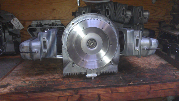
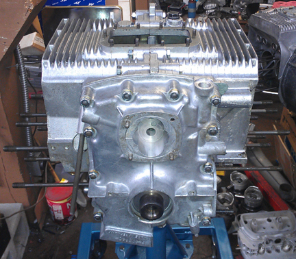
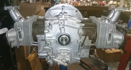
AT RIGHT: This engine after completing the long-block stage and before deciding to build it out as a turn-key. It has a stock 6v flywheel and takes a stock tachometer cable attached at the oil pump.
Contents of this page:
Of course, see the "notable engine features" list above. And, additionally, while this engine started life as a "1600 normal" - type 616/1, during this rebuild, not enough of the original "normal" components were serviceable to justify keeping to in "normal" form, so it has been upgraded with:
 NPR Big-Bore (86mm) pistons
and cylinders, making 1719.4 cc
NPR Big-Bore (86mm) pistons
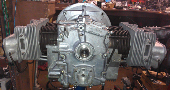
and cylinders, making 1719.4 ccABOVE RIGHT: This engine in long-block form, the flywheel end!
During this rebuild every detail of the long-block has been attended to; nothing was ignored, as documented here.
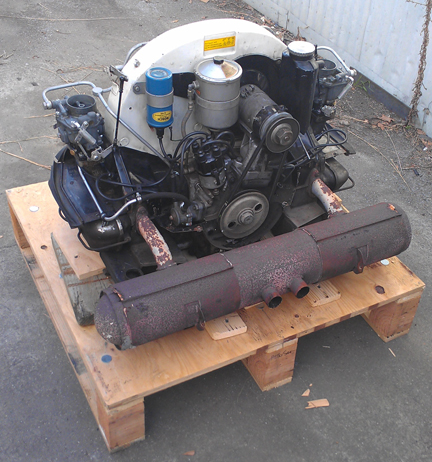
Long ago I received this engine as a core in a partial trade for a C engine.
There was "nothing wrong" with this engine, it just wasn't what the guy wanted. So, upon receipt I put it on the dyno and ran it through its paces.
AT RIGHT: This B engine was in a 356 C and was received as seen here. I sent him back a genuine C long-block using most of the bits seen here to make it run. From what's seen here, other than long-block parts, perhaps only the crankshaft pulley remains with this engine.
What I wanted and got from the dyno run was oil pressure
information. Oil pressure tells you about the condition of the
internal parts, and in particular the crankcase, in a way you
can't get any other way (except perhaps to measure absolutely
everything). This is how Porsche tells us whether we only need a
top-end rebuild or the whole thing.
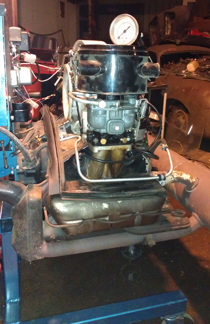
AT RIGHT: The as-run-in-the-C build being Dyno tested. Note the direct read out oil pressure gauge is resting on top of the left air cleaner. From what you can see here, ONLY the long-block, barely visible, remains in this build!
Interestingly, while the oil pressure was fully up to "new"
specification - three atmospheres at 70C (158F) at 2500 RPM with
20 weight oil (20/50 is what I use and recommend) - and even a
little bit more (Nice!), I decided to rebuilt it anyway.
Again, most of these parts went with the guy's C, I just kept
the long-block core. It was completely dismantled as a part
of its evaluation in our trade. Obviously after acceptance, it was
then assembled as follows below.
This crankcase cleaned up nicely and didn't need any special preparation before reassembly. The case is standard bore size and is virtually perfect as is - only needed cleaning. Thorough inspection uncovered no flaws.
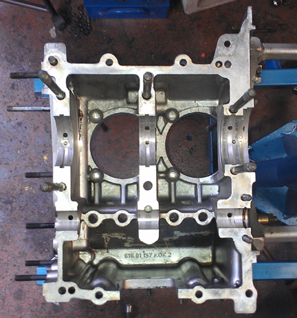
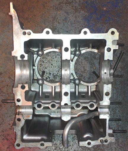
ABOVE: Cleaned and ready to go. The crankshaft bearing bores remain their original "standard" size - no align-bore needed!
Someone had gone nutso on the case sealant on a previous assembly, so I had to take a thread die and run it along some of the studs so it wouldn't interfere with the torquing of the fasteners, but otherwise, no special action was needed.
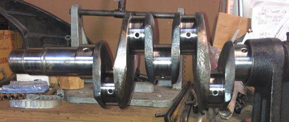 The crankshaft is a B series, just like it should
be. The journals are in good shape and it isn't cracked. So,
there's no reason not to put it back in after a good clean, polish
and balance.
The connecting rods were not OK, however, they were earlier "A" rods. I tossed them into the A rod pile and selected a set of late C/SC/912 rods.
Of course you know, with the exception of the Hirth roller cranks
(or possibly Denzel), I won't put an engine together without
"rebuilding" the connecting rods - too much is at stake; if a rod
lets go at speed (and when else?), the whole engine is lost, and
if either big or little end has trouble, at the very least you'll
have a bad day. ...I also won't put an older rod type into a
younger engine, though, as in this case, I will do the reverse
from time to time. While the late B rods aren't bad, THESE rods
are the best plain-bearing rods Porsche ever made for 356 or 912
engines. ...At some time in the past I - and I'm sure others have
as well - put together images showing all the various rods, and if
you know what to look for, here you can easily tell they are the
late type. ... These are "too good for this engine," but I'm OK
with that.
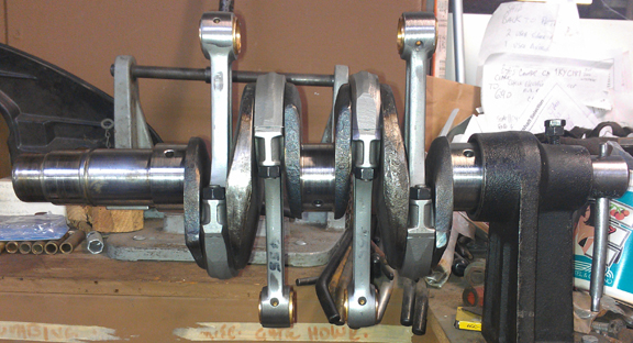
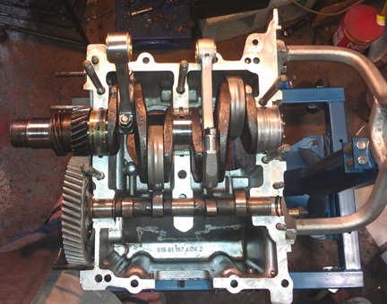
BELOW RIGHT: The crank, ready for bearing and gears. Note the ink used in balancing the rods (recording weights in grams) can still be seen on a couple of the beams, just below the wrist pin. You can also see the line where removal of material on the big and little ends occurred during the balancing process. They're balanced end-for-end and total weight to 0.1g.
 For me, "rebuilding the rods" means
to:
This is all standard work so there aren't any photos of them in-process.
 At first I was rebuilding this one as
"an original 1600" with its original (normal) cam, which was in
pretty good shape, pistons and cylinders and so on. But, after
trial fitting everything, selecting a better (new!) cam gear,
installing the refaced lifters, etc, bottom-end assembled and
about to move on, there was a change in plans due to the fact that
when I got around to actually honing the original cylinders in
preparation to installing them, I found they were NOT in fact
runable.
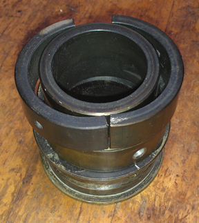
AT RIGHT: The "short-block" going together, act one, with the stock ("normal") cam. The lighting isn't the best, but here you can see it all coming together. The main bearings are old-school Kolbenschmidt (KS on the box) - they're notable for their often dark coloring. I do have a preference for KS bearings. (See bearing image below.)
It was a VERY unusual circumstance to ever needed to do this, but
sometimes, it happens: I tore down the short-block so I could
install a different camshaft to go with the Big-Bore pistons and
cylinders which I usually have on hand. (Usable 82.5 cylinders are
vanishing - in addition to wear, for decades people bored them out
for use in big-bore applications.) ...You might build a true
normal, but with a big bore? Why? You might as well upgrade the
rest of it.
Remember, an engine is a system. All the parts have to work
together! So, the switch to a different cam is an important choice
that's coupled to the choice of pistons and cylinders for the
simple reason that the stock "normal" cam would not have provided
enough breathing to adequately fill those hungry big-bore
cylinders! But that also implies improving the carburetion. And
THAT, frankly, is what prompted completing to turn-key status;
those carbs.
When it comes to engine building, one of my mottoes is:
Cleanliness is next to Godliness!
The cam followers were refaced, of course. All my rebuilds are the whole deal... ...You CAN re-use lifters but only if you keep the lifters in the same position on the same cam in the same case; otherwise you're asking for trouble. It never hurts to reface the lifters! Certainly, if you replace the cam, you must reface the lifters!
BELOW RIGHT: KS bearings have this dark protective coating - a bit odd, and very distinctive, but it does come off. Also note in this image a region of the left half-bearing with none of the coating (near the upper parting line) - sometimes, they weren't fully coated, other times they are and sometimes the coloration goes through weird shades of yellow-green; you find whole KS bearings that are more pale sometimes or one side but not the other, so not having the dark coloration doesn't mean they're not KS, but if they do have it, they are!
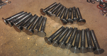
BELOW LEFT: Yes, doing things in batches helps save time. Here's a batch of three sets of lifters that have just been cleaned, refaced and had their stems polished - one of these sets went into this engine.
BELOW LEFT: It is SO RARE that I disassemble a case I'd just assembled, so of course I took photos of what it looked like when I got the case apart after having just been put together! It's interesting to see where the case sealant actually goes! Note the different camshaft! Because the cam is hard to see, there's a closeup, below right - it's beautiful.
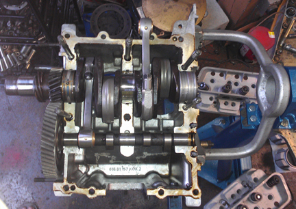

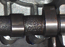
If you look closely, you can see the numbers (upside down) "102" - this indicates it's a "Super" camshaft.
OK, one more time the halves go together! And out-pops a short-block! Yay! (Note all the new hardware.)
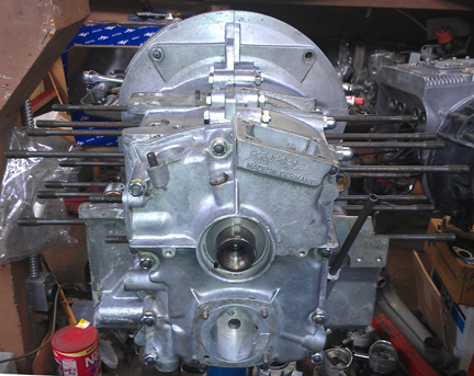 Geez I love how a clean, freshly
assembled engine looks! But I guess I'm a fanatic!
BELOW RIGHT: Yes, more 356 engines are being assembled
now - if you look carefully, there are FOUR 356 engines in this
image, on engine stands, being assembled! Can you pick them out?
No doubt, I'm very passionate about these engines! But then, I
NEED them! The one hard right is the original engine for my '63
production SC coupe, the one behind is for my '59 Convertible D,
and in back, hard left, it's a 912 for my '68 VW double cab pickup
truck!
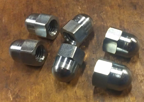
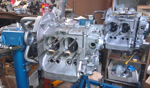
ABOVE: For those who may wish to "concourse" your
efforts, in recognition that it's pretty much impossible to detail
the case acorn nuts without disassembling the engine down to a
short-block, new acorn nuts were fitted! But for those doing a
concourse, on this engine you'd want to do a little more detail
work on the tinware and probably rebuild the generator.
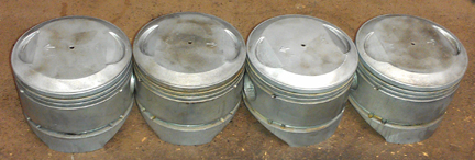
As it came to my workshop, the pistons and cylinders were
nominally 82.5mm in bore, but when it came time to hone the
cylinders, I realized they needed replacement. I opted for a Big
Bore set - genuine, old-school NPRs, the brand that set the
standard for 86mm.
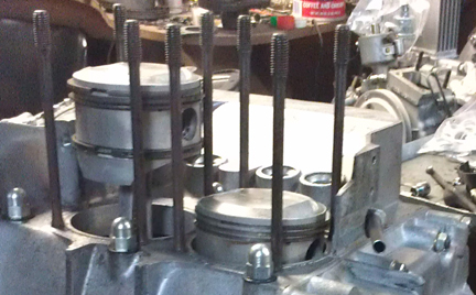
ABOVE RIGHT: NPR big-bore pistons, cleaned, balanced to 0.3g (including pins) and ready for rings.
There really wasn't any choice BUT to replace the stockers because otherwise there'd have been:
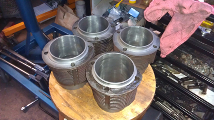
AT RIGHT: The NPR big-bore cylinders, cleaned and honed.
These NPRs are in fantastic condition because some three decades ago I'd built them into an engine that saw only a few thousand miles of service before the crankshaft broke - the second of two I've experienced - and somehow this set was set-aside and forgotten about. (Since then, early 1990s, I now mangiflux ALL crankshafts.) We, the 356 community, have long experience with these pistons and cylinder sets. They are very successful and while they are no longer available, they are the piston / cylinder everyone has copied in the modern era for the new parts we can get today.
Note that this shift to Big-Bore also requires a change to the cylinder heads. There's more on this subject in the cylinder head section below.I always check the match of pistons to cylinders and match piston weights as a set, and provide any remedial action to correct any errors before installation. For example, by shuffling around the connecting pins among the pistons, one can usually improve the matching of piston weights. This set balanced to within 0.3 grams without removing any material - the stock tolerance is 10 grams, so they're nearly two orders of magnitude better balanced than stock!
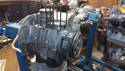
 For many shops, from this point,
installation goes very quickly, but I think this is where one
needs to take one's time! The key reason one needs to take time
here is that there are production tolerances on every part in an
engine, and while a set of parts may look identical, there's
often subtle variation between members of a set, and there
are sometimes significant errors in production that weren't caught
by the manufacturer's quality control processes. These errors can
"stack up" and cause problems if not discovered and corrected.
Two of my steps require special tools even most
356-specific shops don't have.
Here's my process:
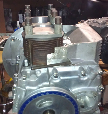
ABOVE RIGHT: Here you can see the height comparison check (for cylinders 1 and 2) - this is done to ensure that there are no difference between the cylinder heights that the head itself "sees." The book value for tolerated error is 0.1mm (four thousandths of an inch), and this engine has no measurable difference between cylinders 1 and 2, or between cylinders 3 and 4. This is remarkable!
I like to carefully measure everything and then mix-and-match the
parts for superior fit. I have also discovered significant
manufacturing errors with this process which would likely have
gone unnoticed without these measures. It is remarkably easy, for
example, to overlook the circumstance of the crankshaft bore not
in the true center of the crankcase, angled on the horizontal left
or right of center, or not on the same horizontal plane at all.
Yet examples of errors like these are not as uncommon as we would
like. ... Over coffee or beers sometime I can tell you about some
of the more egregious manufacturing errors I've seen get past
Porsche!
 The next thing I do is something
nearly nobody else does in the engine building process, and
that is to measure the height the piston crown comes above the
plane of the top of the cylinder. I call this the CAC, or
"Crown Above Cylinder." This value is important because, firstly,
it can reveal deeper problems, and because it helps get the
compression ratio equal in all four cylinders.
Note that for this aspect of the work, most other people
either use clay or a liquid, but this isn't accurate enough
for me.
With clay, they let the piston squish it against the head, then measure the thickness of the material upon disassembly - effective, but not particularly illuminating on the points made below; you only know the gap, but not which side is contributing any discrepancies, the head or the piston. And neither does filling the combustion chamber with liquid, as many shops do; liquid just doesn't provide this kind of information either.
Here are some of the deeper problems that can be discovered through a CAC check:
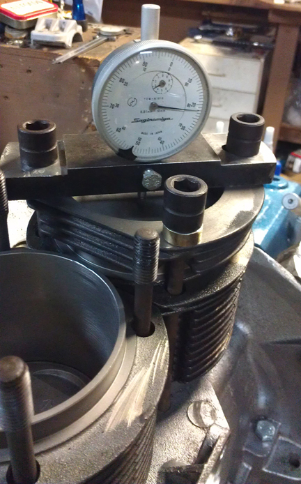
ABOVE RIGHT:Cylinder 3 having its CAC value measured. All four cylinders are measured this way, and should any significant difference be found between cylinders, swapping pistons, cylinders or even rods around can help make a better match and find out exactly where the discrepancy may lie. This measure is extraordinarily accurate.
In order to do this for these engines, you have to have special tools. Here, you can see them in action on these images.
The distance between the smallest tick marks is one hundredth of a mm, or 0.0004", and you can discern to perhaps a tenth of that! So, this is a very accurate measure, performed while the cylinder is under torque, so any shims are squished flat, etc. In this instance, the heights at which the pistons protrude above the plane of the top of the cylinders were all remarkably close, within 0.07mm on one side and 0.085 on the other, well within tolerance (which is, by the way, unspecified by Porsche - Porsche only specifies the maximum difference between combustion chamber volumes under one head), which, in this case. This means Porsche ignored such errors entirely. However, with a linear measure, piston crown volume, bore, etc, these effect on combustion chamber volume are easily calculated.
The accuracy of this measure is so good, that if you take the time to swap parts around, you can accurately determine discrepancies in the manufacture of the various parts! But, we ARE splitting hairs here! However, a benefit to both engine builder and the resulting engine is that the ability to move parts around for better fit means that perfection is more easily achieved, and the more equal the HP production of each cylinder, the smoother the engine will run, and the more HP the engine will produce overall.
Because this process includes the entire assembly, torqued as in service, and measures the height each piston protrudes out of its cylinder, all errors in connecting rod lengths, cylinder heights, crankcase spigots depths (cylinder bore deck), piston connecting pin heights, and shim thickness' are accounted for in the measurement results. There is no superior method.
 The heads had zero observable
problems as the engine was dismantled, and the heads weren't even
particularly dirty, but, as stated elsewhere, my idea is to have a
consistent, reliable build, so the heads received my standard
treatment:
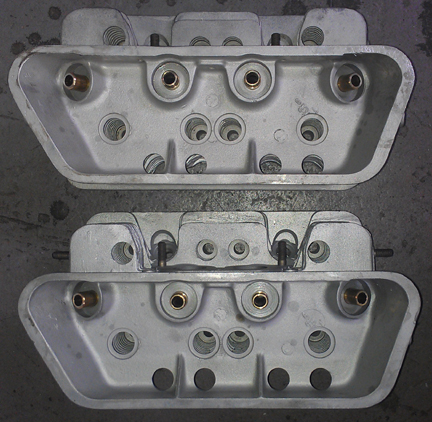
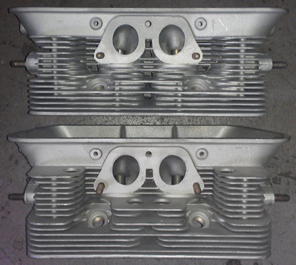
ABOVE RIGHT: No broken fins, no cracks, no bad threads - these heads are in fine shape. ONE exhaust stud needed replacement.
AT LEFT: these heads with new guides installed. You can
tell they're late B because of the triangular gussets in the lower
"rocker-box" area.
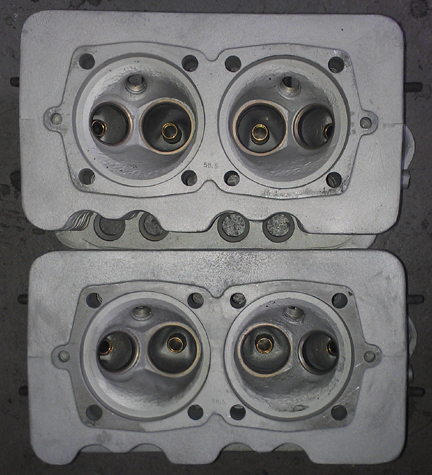
One thing that was apparent as the engine was dismantled was that someone diddled with the combustion chambers with a die-grinder, presumably to try and match up the combustion chamber volumes - at least that's what I presumed as I cleaned it. However, a second realization came to light later.
It turns out that the original combustion chamber shape changed by 8 degrees from the B (and earlier) era to the C era (including SC and 912), and the NPR Big-Bore sets were designed for the later shape. The good news is you can take material out of the earlier head to get it to match the later shape, and you must do this if you are fitting NPR pistons.
During assembly it was realized that these heads were already
clearanced for the Big-Bore pistons through this die-grinder
activity, whether intentional or not! In carefully examining the
work it is most likely that indeed this was the purpose because
the material was taken out all around the edge, just where an
interference would occur. And, thankfully, they didn't take out
too much, either! If someone wanted to, the compression ratio
could be raised to over 9.2:1 without too much trouble, though
with today's gasoline, that's not advisable. Instead, I planned to
set it to about 8.5:1, which is a modest increase over stock, but
when it was a bit higher and consistent all the way around, I
didn't bother trying to lower it; 9.0:1 is the highest I'll go
without a quite deliberate effort to make a top-performing, 6k RPM
engine such as an SC or 912 - or, on request, of course! But with
> 9.0:1 compression, you'd BETTER have great ignition timing,
air-fuel mixture AND ONLY run higher-octane fuel.
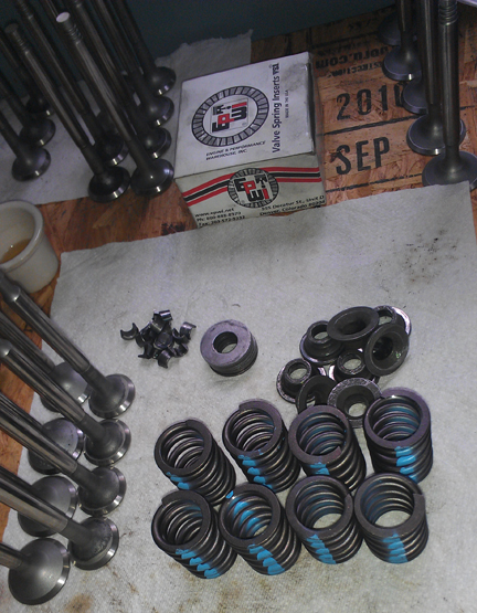
AT RIGHT: The valves (foreground left), springs, shims, retainers and keepers used in this engine, ready for assembly.
Long term running experience illustrates that the stock spring pressure is a bit light at 61.5 lbs @ 41mm, and with such pressures it was not uncommon to have an occasional bent valve when it can't get out of the way of a piston - I've even had it happen to me! And, as a practical matter, drivers tend to push their engines until the valves float - a risky situation! So experienced 356 / 912 engine builders have been using stiffer springs for a great many decades.
Given the Big-Bore pistons and cylinders and the Super camshaft, it seemed prudent to plan for higher-RPM. With SC and 912 engines, a typical choice is 90 lbs, or more for enthusiastic drivers, to, say 100lbs or so, but this engine type was never intended to run to 6000 RPM (no counterweights on the crankshaft, etc.), so these springs are a compromise at 85 lbs - still more spring pressure than genuine C / SC / 912 engines, providing more protection against floating the valves, but without unnecessary "internal losses" in compressing the springs since presumably this engine won't be driven at 6K rpm except in an emergency.
Also note that I always match up slightly stiffer springs with the heavier valves (intakes are about 2% heavier than exhausts), so they're very close sets, matched up, so all the valves tend to float at the same time.
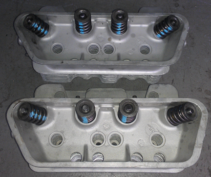
However, in this case, all the springs were virtually identical - a somewhat unusual circumstance. ...Of course, each valve and retainer are position-specific through the shimming process as the spring-heights are set. This close-matching of spring tensions helps the driver know when they're over-revving because all the valves will tend to float at exactly the same time, thus sending the clear signal of a drop-off in power. When one or two valves float before the others, the driver may not realize they're harming the engine and continue on, getting into trouble!
AT RIGHT: Here they are, ready for installation.
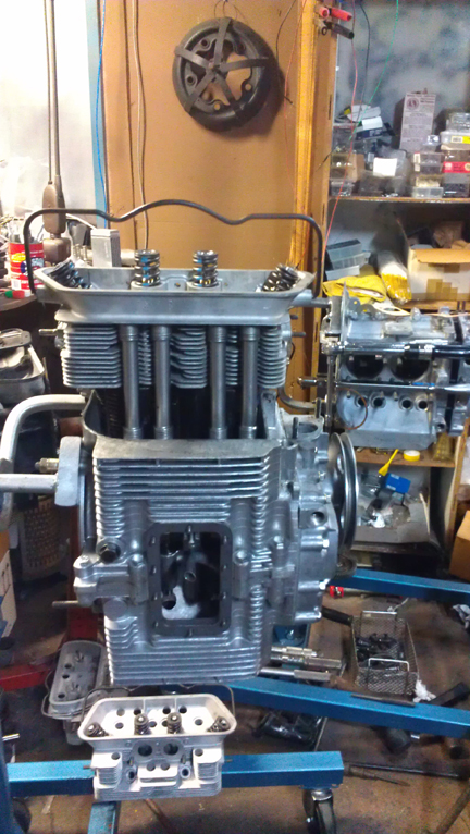
At this point the engine is ready for its cylinder heads, and this work went very quickly - as it should! - as all the prep work was already done.
Prepare the head "bolts" and washers, prepare the pushrod tubes, prepare the lower cylinder air deflection plates and their wire retainers, and get the torque wrenches set, and bolt on those heads!
My pattern is to mount one head, torque it to 7 ft lbs, then mount the other head the same way, and then alternate between the heads with an ever-increasing torque up to the final torque value, then repeat the final torque value until the fasteners no longer turn when torque is applied.
Then mount the valve gear, adjust the valves and pop on the valve covers. Yeah, sounds simple, but, to do a great job, there's more to it than that...
Then fit the oil drain plug, and sump screen and plate. I painted the sump plate with rattle-can black... Then, fit the two oil control pistons and the oil pump. Both oil control piston springs were replaced with new along with one of the two oil control pistons.
...The careful engine builder is constantly running into problems like either worn out rocker arm contact faces (where they contact the valve stem), or mis-ground by someone who didn't have the wherewithall to grind them properly, as happens all too often, and as can be seen here.
BELOW LEFT: Here's a mis-ground rocker arm someone "refaced" in the past. Note how the rocker is only making contact on the extreme left edge of the valve stem! The result of this situation is both excessive wear of the valve stem and also that a "pocket" develops on the rocker arm, making valve adjustments difficult! The rocker was, no doubt, refaced "by hand".
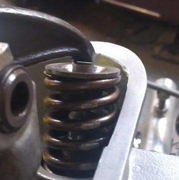

ABOVE RIGHT: Of course the correct thing to do is what I do; reface the valve rocker's valve-stem contact faces (and polish the shafts).
On the later engines, which have a different metallurgy, I "hard face" the rockers, a three step process of refacing, welding new material on and then facing the new material. ...I'd overlooked taking photos of the ones in this engine, so these, both above left and above right, are from another build, but they illustrate the point.
Happily, the earlier rockers are made of a harder material and don't need this process; a simple - and correct - refacing (based on the pivot axis of the rocker shaft) and they're good to go.
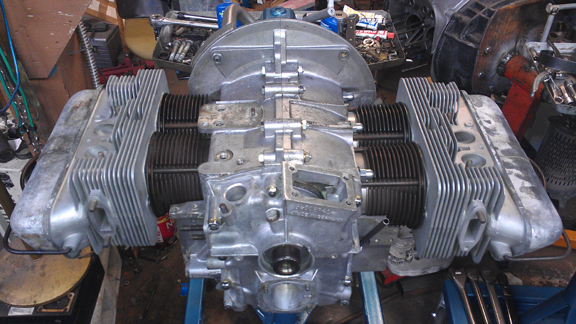
AT RIGHT: Here's the completed longblock. ...Almost. The
flywheel will be mounted after it's taken down from the engine
stand - and the oil pump still has to be mounted!
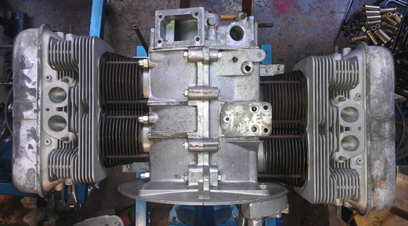
The flywheel is a stocker (180mm, 6v ring gear), in fine shape - well, at least it is now, after I cleaned it up and refaced the friction surface. I didn't fit a pressure plate to it because this engine could be put into an earlier or later car and there are two different pressure plates one might choose from - better you choose! Or, just run your old one! (I can mate it to the flywheel and balance the two together for you if you'd like - this is highly recommended.)
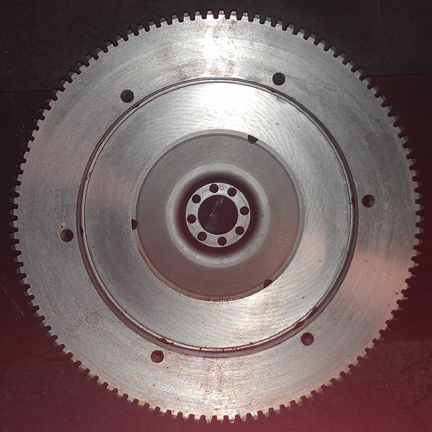
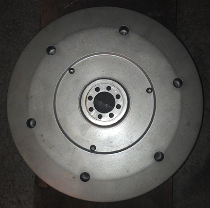
ABOVE LEFT AND RIGHT: Just doing a thorough job - the flywheel was thoroughly cleaned and then resurfaced. It has a lot of life left in it. That warm red glow was caused by sunlight reflecting off something in the workshop - I kinda like it.
 Some of these topics have a
section below, some don't. Here's an overview:
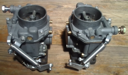 As noted, I had these genuine Super
Zenith 32 NDIX carburetors rebuilt by 356 Carburetor Rescue,
the best in the business, during their last months of operation
after decades in the business. (As of this writing, they've stopped
rebuilding carbs and are selling off existing inventory.) These are
setup as for a B-era Super, but jetted for
this engine.
AT RIGHT: This pair about to be mounted.
As noted elsewhere above (I think?), these were 1600S carbs from new and have the larger venturis.
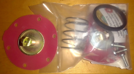
I used the earlier "A / B" fuel pump, and rebuilt it using a special, alcohol-safe diaphragm since different parts of the world have significant percentages of alcohol in their fuels.
AT LEFT BELOW: You can see the alcohol safe diaphragm to the left of the standard rebuild kit. Note the difference in the color of the plating, a yellow instead of silver.
AT RIGHT BELOW: The "core" used for the rebuild. As noted, its internal lever-arm assembly was badly worn and was replaced with genuine NOS parts.
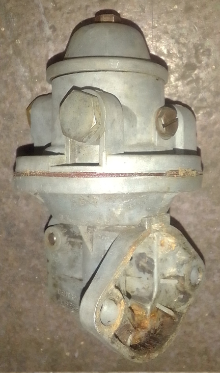
The pump happened to have a bad lever mechanism inside - VERY
badly worn - so I replaced it with the quite rare '50s to '60s era
NOS lever arm parts. I have no more of these as old stock but I do
have some of these, also NOS, from the 1980s and they're nowhere
near as good, unfortunately, which might be why they stopped
making them!
I didn't happen to take a photo of the pump and its
mounting bracket and thermal spacer before mounting to the
engine.
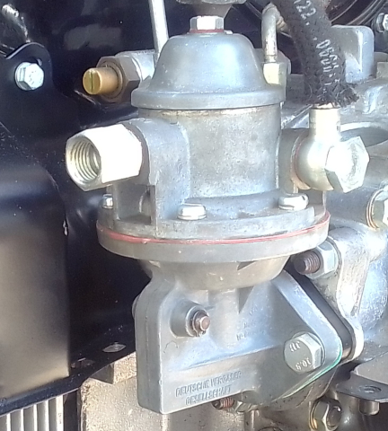
BELOW: Second best, I have this closeup of it, mounted. Note that you'll want to swap over your oil temperature sending unit because the gauge and sender must be mated to one another... Talk to Hartmut at Palo Alto Speedometer for more about that one...
Note that for the few short bits of fuel hose used, it, too, is
the new Choline (OEM) brand, E-10 safe version that suffers our
modern fuels far better than the older hose does that some people
still use.
A new, modern production OEM Beru ignition wire set was installed
- new grommets, etc - and these were plugged in to a new Bosch
burnt-sienna colored cap. The coil is an original Bosch,
repainted, with screw contacts. The distributor is an original for
this year and application, Bosch BR18.
The distributor got a new condenser and holder as a wrong type
condenser was fitted, and the two cap clip mounts weren't in great
shape, either, so they got swapped. The rest, including in my view
the paint, still has great original patina and so I decided not to
repaint it as I went through the process of giving it some love
and attention. ...I just gave her what she needed, not a complete
makeover.
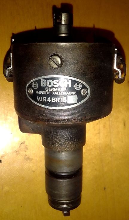
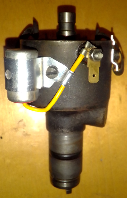
Of minor note, I also replaced the condenser to coil wire and at
first thought the coil had a spade connector, so the image above
has a spade connector to join them. However, when I saw the coil
has a threaded connector, I switched and so it's "old school" now.
The engine has three pieces of tinware that are from a 912: the
fan shroud and both flapper boxes. They're in great condition and
there are available new lever arms to convert the heat flappers
from 912 to 356 use, but I've left that for the new owner.
Meanwhile, there are only a few other 912 parts on the engine and
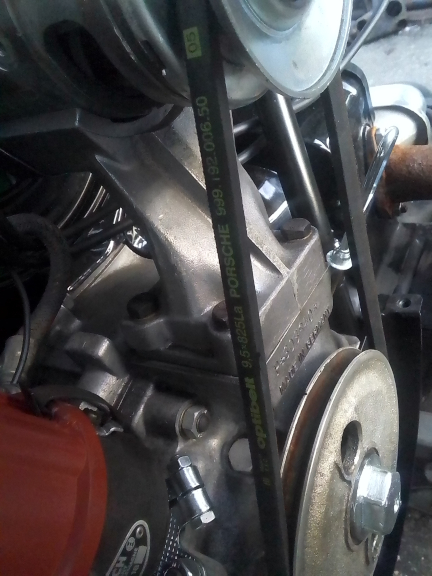
this image shows the 912 pulley and pulley bolt, and along for the
ride is the new, genuine Porsche fan belt! Hey, it's what I keep
in stock for myself! (I think I installed new pulley parts,
too...) Below, you can also see the dip-stick is plated as well.
Of course I mounted this up to my Stuska engine dynamometer and ran it to be sure it was all AOK!
...I've got some more images to put here, but there's an image of the engine on the dyno up at the top of this page...
Some people are keeping logs of VIN and engine numbers and then purport to tell people what someone else has; out of respect and concern for privacy, exact VIN and engine number data are not published here.