Copyright © 2007 - 2026, Richard Troy For contact data Click Here.
Copyright © 2007 - 2026
Copyright © 2007 - 2026, Richard Troy
For contact data Click Here. ![]()

This engine's rebuild has been done far more comprehensively than
most and has many upgrades such as a 356 C crankshaft, new Webers,
356 C type intake porting, big-bore, etc, and will produce more
power than an original 1600S. The details are, of course, below.
This engine is from a T6 era 356 B and is perfect for use in a
356 C, SC and with a change of the oil breather / filler, it would
work great in any 356 because it has a new pressure plate that
works with early and late throw-out bearings, as described below.
Wire-mesh air cleaners (moderns that look like the Solexes) and the surrounding tinware are all available; I didn't mount them for two reasons. First, over the decades most customers have told me they have these pieces already, and second, there are (at least) two different air cleaner configurations and also different shrouding options. That said, tell me what you need as I likely have on hand beautiful examples ready to go!ABOVE RIGHT: This engine during the run-in / tuning process on my Stuska water-brake Engine Dynamometer. To see it running, Click here.
From Porsche it was a late 356 B 1600 Super, but now it has a 356
C crankshaft, C head porting and manifolds, and a tried-and-true
Big Bore set of pistons and cylinders making 1719.4 cc. The
carburetors are new Webers made by Weber North America and sold by
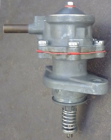
Redline, and both the distributor and fuel pump have also been
rebuilt.
This engine features:
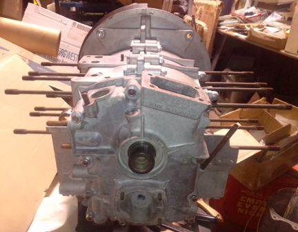
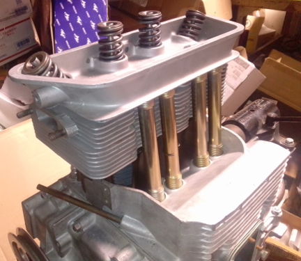
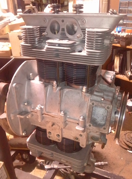
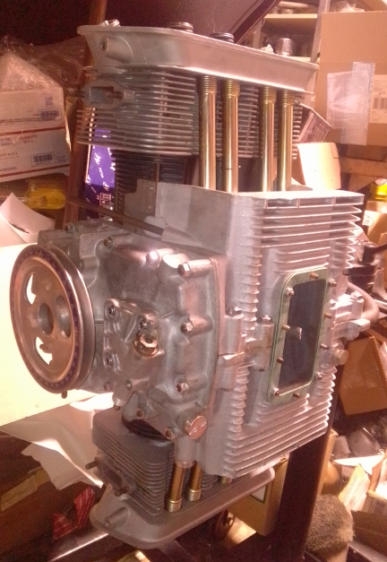
AT RIGHT: This engine at the long-block stage, just before finishing it off. Note that all reasonable opportunities to replate the hardware were taken.
Find on this page:
The crankcase dates from the first half of 1963, the end of the
T-6 356 B era which concluded on July 31. When I got it it was
wrong for the car I'd bought but I rebuilt it and enjoyed the car.
Eventually another, closer engine to the car was found and I sold
this engine off. It then came back to me and I went through it
again, top-to-bottom.
When I first got it, it was built from parts from many different engines and when I got it back it had even more different engine parts on it! But on this last cycle, I rebuilt it according to a strict process and corrected many of the issues with it, gave it the better C crankshaft, 356 C porting on the intake system a slightly "hotter" camshaft, etc, as told below.
This crankcase is the very youngest, most advanced of the 356 B era and includes the "anti-shuffle" tubular alignment dowels that locate the two case halves at the center of the crankshaft, one around the upper stud, the lower around the through-bolt. I'm not aware of any further updates to the case until the 912 era.
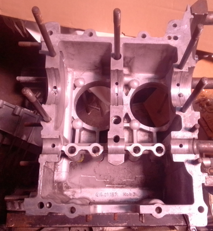
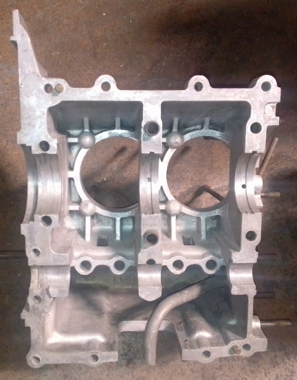
The crankcase was cleaned and inspected and found to be in good condition. The crankshaft bores were checked, cylinder deck heights confirmed identical, and so forth. I once got caught with a cracked lifter bore discovered after the assembly was in progress so I'm sure to check most everything fairly thoroughly before assembly begins. The timing cover can be seen during assembly below.
The core's crankshaft was an incorrect choice, an "A", while the engine is a B. They were known to Porsche to crack under heavy service so, as the engines got more powerful, Porsche moved on to the B crank in the summer of '59. However, while better, even these cracked frequently enough that Porsche then increased the middle main bearing journals nominal size from 50mm to 55mm and this helped a good bit.
 I therefore selected a C
crank, which has 55mm middle main bearings.
I therefore selected a C
crank, which has 55mm middle main bearings.
AT RIGHT: This "C" crank has been magnifluxed to check for cracks, ground as needed, then cleaned and polished. Yes, that's a new distributor timing gear.
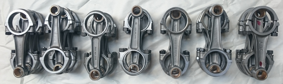
The rods I selected are the next-to-last type and perfectly fine for this application. So, the rods got the usual treatment of cleaning, checking, rebushing, resizing the big end, boring the bushing to ensure all four have the same length and then balancing for both end-for-end and total weight weight. Thus, I then have the crankshaft ready to go, as seen here.
BELOW: This set is probably the second or third from the left. I do them in batches like this because it's more efficient. They all get balanced end for end and total weight and and the bushings are cut to ensure each set are exactly the same length.
With a good crankcase, assembly usually goes well, you just need
the right main bearings and I had an old-stock set (Glyco brand -
high-quality, old-school).

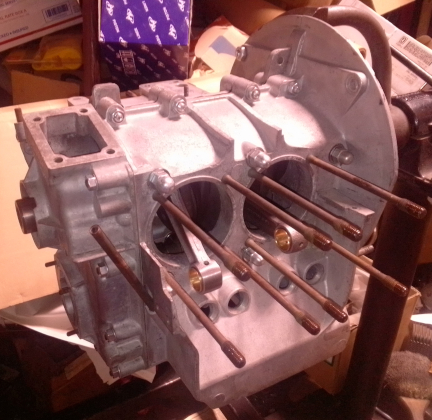
AT RIGHT: Lifters inserted, flywheel bearing dowel inserted, bearing halves installed then lubricated and flywheel main lubricated then installed, and crankshaft laid in its half.


ABOVE & BELOW: Cam gear selection took a few tries before I settled on the new one above.
The cam gear bolts were upgraded to new 10.9 grade, service-removable thread-lock applied and torqued to 18 ft lbs... And here are closeups.
This is a brand new cam ground specifically for a street use and
to take advantage of the bigger bore and better breathing .
I forgot to take photos of the inside of the timing cover. Oops!
The old ones were "big bore" - 86mm (nominally) - and in bad condition. So, I replaced them with modern production, which I suspect is of much higher quality since modern metallurgy matches piston coefficient of expansion with cylinders. In this case, they're "cast - cast", meaning the cylinders are simple iron castings - durable, long lasting, and the factory's choice for most engines - and the pistons are also cast, a technique Porsche used on all their 356 engines, including the four-cam Carreras.
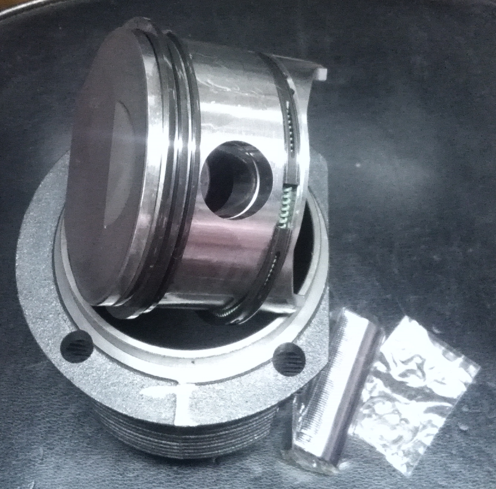
AT RIGHT: One of the piston and cylinder sets that's going into this engine, along with its pin and pin circlips to the cylinder's right, both still in their original packaging. These are balanced as a set in total weight to 0.1g of one another.
My process is to de-ring the pistons, clean them, weigh all pins
and pistons separately, match heavy pins with light pistons, then
remove material from the heavy pistons to match weights and so
balance them. As noted above, my tolerance is 0.1g for the weight
spread among all pistons in a set, fully two orders of magnitude
better than stock tolerances (10g vs 0.1g).
I also VERY thoroughly clean the cylinders
because they will have the left-over dust from the honing
performed during manufacture. This dust is typically extremely
hard material so manufacturing can go quickly and this will embed
into pistons if not fully removed before use. Said material, once
embedded in pistons, will wear out the cylinders far faster than
if they'd been cleaned. Since nobody will ever know until LONG
after the fact (and likely still not know), this is one of
those hidden advantages of an engine from a skilled,
knowledgeable, and passionate builder vs someone who
either doesn't know or doesn't care.
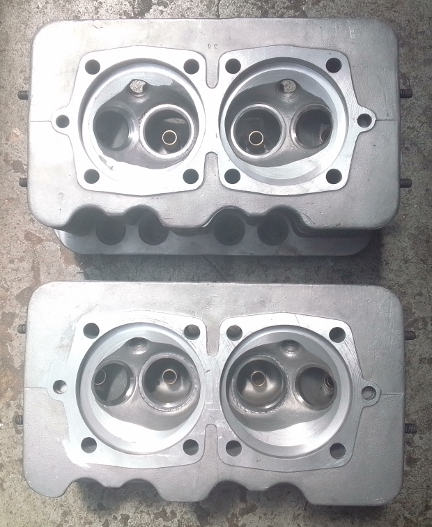
Long ago when in my hands it had B heads, but in this instance it
had A heads. I of course swapped them back to genuine B heads that
I'd already ported to C/SC/912 intakes for a different project
that ended up with 912 heads instead. As noted, I opened the
intake ports up to match the later C. And, I cut them to take the
later 30 degree crown pistons.
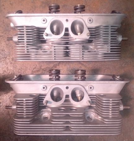
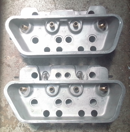
BELOW LEFT & RIGHT: These B heads have had their intake ports opened up to 356 C dimensions, new guides have been installed, and they've been both decked and flycut. A conical, 30 degree cut was performed to clearance them for use with later piston sets. Note that one head had a cracked valve guide boss inside the intake port which I welded up (left image, lower head, right port).
Heads of this type, B series, in particular, are not known for
cracking but a valve guide support boss on one of the intake ports
was cracked due to improper valve guide replacement, so I welded
it up and fixed it correctly.
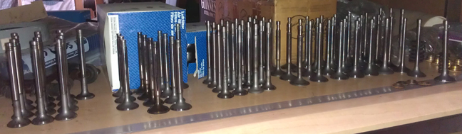
I always stock plenty of valves that have all been cleaned,
refaced and stems polished from which I select the set of valves
to be installed:
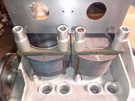
AT RIGHT: I leave the piston rings off after balancing, as noted above, thus permitting easy checking. Here I install them in cylinders, locked down with special fixtures and make sure the cylinders are in the same plane.
Late cases are much more dimensionally stable so having a tilted
cylinder is rare for reasonably cared for engines but I always
check. Here, they were fine for both pairs, well within the 0.1mm
tolerance.
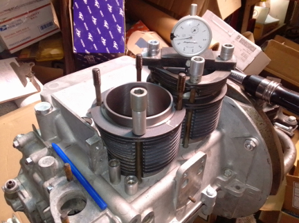
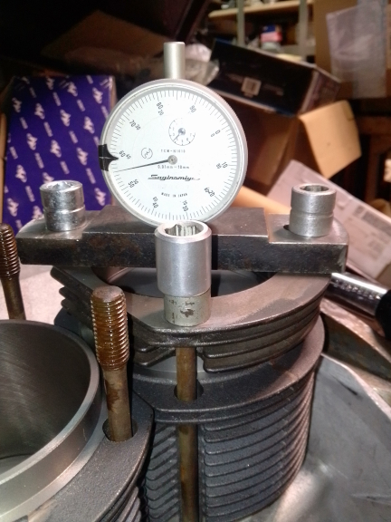
I moved on to measuring the crown-above-cylinder (CAC) height.
This data, combined with knowing the crown-volume of the
particular piston design and a few related factors, gives me the
exact reduction in combustion chamber volume for the given
assembly.
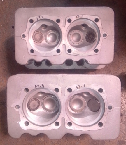
Remarkably, there are very nearly always differences between
cylinders on one engine, fundamentally due to "tolerance stackup"
of things like the bore angle of the crankshaft in the crankcase,
piston manufacture and so forth. Given cylinder head combustion
chamber volume data (seen written on the heads for each chamber
above), this gives me an opportunity to move parts around to make
a better build and only after having done so do I remove any
material to balance the engine completely.
This gives me a vastly better build more easily than most can
manage. The vast majority of engine builders skip this entirely or
feel they need to make EVERYTHING perfect. Everything doesn't need
to be perfect, "matching the blueprint;" all the cylinders just
needs to match all the others on a few critical parameters!
Building higher than 9:1 compression ratio is risky if there's
any chance the owner will run less than 91 octane fuel, run less
than damned close to perfect mixture or damned close to perfect
ignition timing. Therefore, I aim for 9:1 on street engines unless
specifically requested otherwise. If it ends up at 9.1:1 I won't
complain but 9.2 is my upper limit. This one clocked in at a touch
over 9.0:1.
Time for the heads, prepared earlier (and they must be in order
to set the compression ratio). To mount them, I need the mounting
hardware, but, typical for cores like this, it came with
mismatched "head bolts". I set them right and replated, too:

ABOVE & RIGHT: Curiously, as they came out the above head bolts have different seals from the previous build (?!). There were also some longer (earlier) head bolts - it was mis-matched. I corrected this. AT RIGHT: An example of the hardware replated, showing I did the interior as well as exterior hardware, as noted elsewhere.
The plating is "clear zinc." The tube is in the timing cover and the cup is the camshaft end plug, etc.
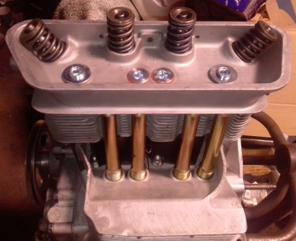
Now, the head are installed along with air deflector plates and
pushrod tubes, of course!
Now, the rockers. When I first got this engine more than 30 years
ago it had "the late rockers," but they were fouling on the valve
retainers. I happened to consult about this with Harry Pellow, a
fairly notable guy in the 356 world at the time with a number of
great books to his name. I asked. He said that on the B series,
"sometimes you get away with running the late rockers, sometimes
you don't!" Late here meant C/SC/912, and the only exception I was
aware of was the S90 series. So, having had this issue, I swapped
on the iron rocker stand version later didn't think about it.
However, an alert potential buyer commented that given the picky
356 buyer of today I should finish the job off better by running
the correct rocker system?! I then realized my error and have
responded by replacing them as seen here.
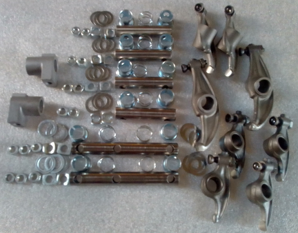
AT RIGHT: These are the rockers, shafts, and all the additional hardware actually fitted. The rockers have been blasted clean and "refaced" to remove The shafts have been polished. Note that the shafts look dark due to lighting and how the cell-phone-camera doesn't handle low-light conditions well. When I tried the flash, the brightness of the shaft hardware made the rockers look dark!
Also around 30 years ago (early 90s), give or take, I noticed how
the "late rocker" base material is very soft and once the surface
hardening is worn through (unlike the earlier rockers), wear makes
it very difficult to maintain proper valve adjustment, and around
25 years ago (late 90s) I learned there's something we can do
about it, it became my policy to reface ALL late type rockers as
described here. ... Of course, as with all engines I rebuilt, the
shafts are polished, they get new adjustment lock nuts, etc.

Note that refacing the late rockers requires several additional
steps over their earlier counterpart:
AT RIGHT: This set has been refaced as just described.
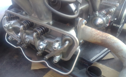
I didn't happen to take any photos of these rockers mounted until
after the engine was off the dyno, but now we have this:
 Flywheel & Pressure
Plate
Flywheel & Pressure
PlateThe original 180mm system was adequate, even for Super engines, back when we could get asbestos clutches. However, designed for a 20 PS (25 SAE HP) engine, it was at its limit; Porsche knew it and had already created the S90 200mm system.
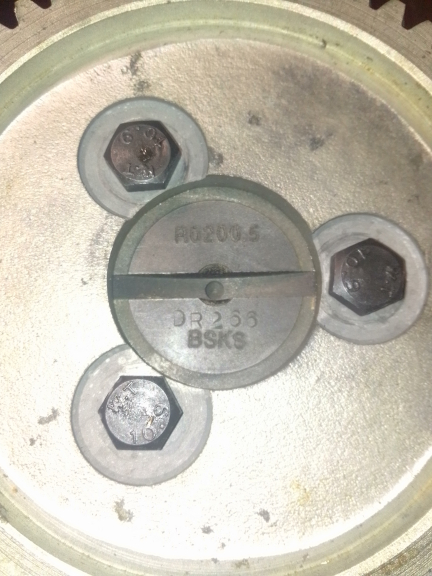
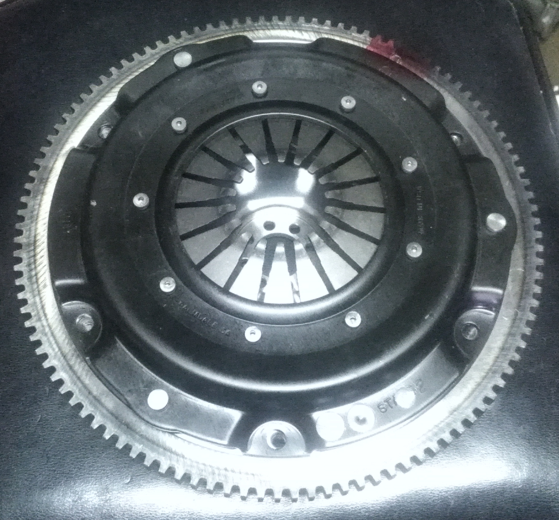
AT RIGHT: The new flywheel and pressure plate. The red mark at about the 1 o'clock position is the balancer's mark. Less visible, there's also a stamp in both parts, so proper reinstallation even after washing will be easy.
Since asbestos clutch disks evaporated over 30 years ago, only
weak engines can get by on a 180 with a standard,
modern-production disk and this engine will produce far more
horsepower. You CAN upgrade the friction material or pressure
plate but its simpler and have easier parts sourcing with a 200mm
system, so that's what I provided.
This unit works on ALL 356 transaxles!
For early cars, an available "release collar" is
required. Later cars run this as-is.
Remember, the late throw-out bearing is
CLUTCH DIAMETER related, NOT vehicle model related!
This is an all new 200mm unit with 6v ring gear - of course! - a
VW clutch depth and a Kennedy brand pressure plate that has been
proven for years to work quite well at reasonable cost, with lower
cost and far more readily available clutch disk. It also has the
benefits of, firstly, being convertible for use with transaxles
from before August 1, 1959, and secondly, of being entirely made
in the USA!
As noted above, the pressure plate chosen has an option to work on
the earlier cars. As provided above, it works on all later 356 B
and C cars which use a guide-tube supported throw-out bearing.
Because it's a 200mm clutch and because the C cars came stock with
a 200mm flywheel, the C type throw-out bearing is the one to use -
the T/O bearing choice is CLUTCH DIAMETER based NOT car based as
some vendors (and the manuals) might lead you to believe.
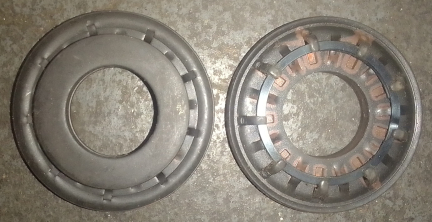
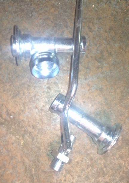
AT RIGHT: Here's the optional Kennedy release collar that fits onto the pressure plate type used on this engine (seen above), and thus converts it to the earlier type of clutch so it can fit in any VW or 356 not using a guide-tube throw-out bearing. If you need one, let me know, I usually have one in stock.
BELOW: Both sides of the new flywheel. Note that there are several manufacturers of these today and this one is from a better vendor and I also carefully check them and reject ones with any issues. Note in the image at left, along the bottom rim, the three holes; these are ones my balancer added to balance the flywheel, by itself, before balancing with the pressure plate. This permits the pressure plate to be replaced more readily, if necessary someday.


 Porsche calls the
components used to convert a long-block to a running engine
"accessories." These include the carburetion system, the fuel
system, the ignition system, the engine cooling system, and the
exhaust system.
Porsche calls the
components used to convert a long-block to a running engine
"accessories." These include the carburetion system, the fuel
system, the ignition system, the engine cooling system, and the
exhaust system.Here are those Webers. Note the round stickers indicating they
ARE genuine, licensed Webers! Further, they come with a warranty!
It doesn't hurt that they're also consecutive serial numbers. Note
also the new downlink rods.
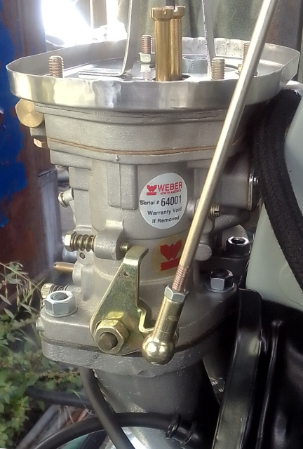
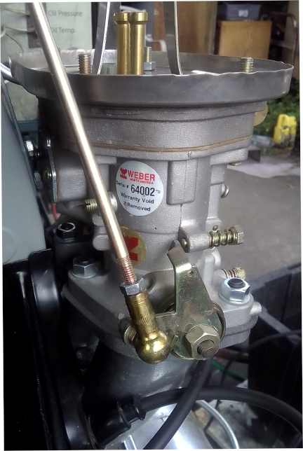
It shouldn't escape notice that I fitted new ball sockets (all 6)
and rods (all three) for all three throttle linkage "downlinks"
connected to the long cross bar, not to mention replacing all 8
special M8 X 12 ATF nuts that retain the carbs to the manifolds.
The manifolds got similar treatment ... as did the rest of the
engine.
When the engine left me last it had an original "022", cast-iron
housed distributor, but it came back to me with an aluminum housed
"031". Both are legitimate for use here but 022 is assembly line
and 031 is replacement. You can see the unit in other images of
the complete engine. Here are the guts.
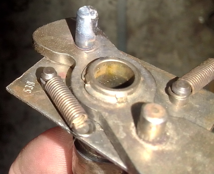
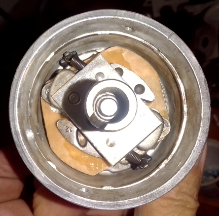
ABOVE LEFT & RIGHT: At left is the distributor's advance limiting peg, which was well worn, having been welded up and reshaped to "remove" the wear. At right is the inner assembly from above and as can easily be seen the micarta plate the advance weights slide on has been replaced, lubrication easily visible. Further, in both images, the "double ended single loop" springs, the toughest ever used and long not available new, are still in service. Further, in the right image one flyweight can be seen to be a "double" and another "single," thus reflecting an adjusted curve using the same technique Bosch itself used during the period of manufacture sometimes: Most had two double flyweights, some had one double, one single, like this. (This I learned circa 1990 from Richard V. Lukes, famed engine builder of Lukes & Shorman in Berkeley CA.)
The oil sump plate magnet was found to be leaking oil through the rivet. This was confirmed by easy rotation of the magnet, so the rivet was renewed.
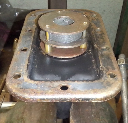
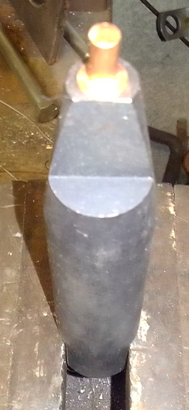
ABOVE & AT RIGHT: The anvil is mounted into a vice, the rivet placed upon it, then the sump plate, and finally the magnet. Then, the rivet is crushed and the job is done. ... I normally paint, or even powder coat, the sump plate before this is done and I'm not sure why it wasn't in this instance! But, painting after is about the same as painting without doing this job!
AT RIGHT: Here the engine is after run-in and tuning on my Stuska Engine Dynamometer.
Some people are keeping logs of VIN and engine numbers and then purport to tell people what someone else has; out of respect and concern for privacy, exact VIN and engine number data are not published here.